How to Build a Cantilever Gate Cable Truss System
Instructions for installing a cantilever cable truss system
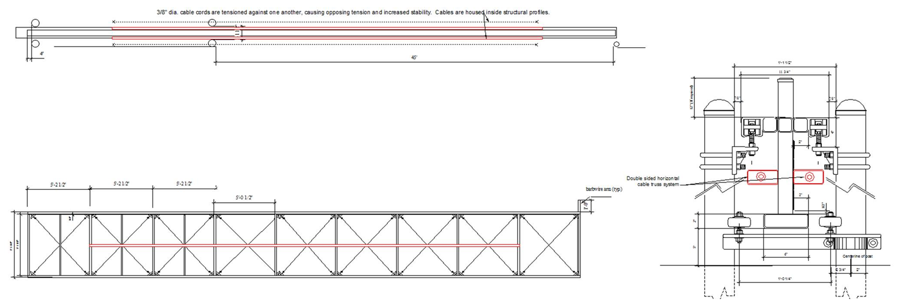
The below installation instructions are for installing a horizontal cable truss on a steel cantilever gate. The illustrations are installation of a cable truss assembly on an aluminum cantilever gate. The intent of the a cable truss system is to provide a non-obtrusive, inexpensive yet effective means to prevent cantilever gates from swaying-out of alignment under wind load. The principle is establishing an opposing tension between the two cable assemblies to the point that the tension not only is equal between the two assemblies to keep the gate straight but so great that the gate cannot be pulled to either side. If the gate were to be pulled to any one side, the tension or pull on the opposing or opposite side of the gate will increase exponentially while the tension or pull on the same side as the gate is moving would decrease exponentially. This causes the gate to immediately be pulled back straight or until the tension is equal between both assemblies.
- Install 2 ea. 2” x .090 tubes at the midpoint of the gate.
- These tubes should be offset 1” from the face of the gate.
- The tubes run horizontally across the entire length of the gate. The illustration below shows the truss stopping at the midpoint of the tail section. This is acceptable but not recommended.
- The offset can be achieved by notching 1 ½” long x 1 5/8” O.D. pieces of tubing and welding at every upright. It is important that the tube is attached at every upright.
- Build 2 ea. cable assemblies. The cable should be no less than ¼” diameter and run the entire length of the gate.
- On one end of the cable assemble, form a small loop by looping the cable back and fixing with three ¼” cable Crosley clamps. The loop should be large enough to run a 3/8” rod through it.
- On the other end of the cable, attach a 12” x 3/8” threaded galvanized rod with a small ring welded on one end.
- Loop the cable through the ring and loop back. Attach with 3 ea. ¼” cable Crosley clamps.
- The total length of the taught cable assembly should be no more than one inch longer than the tube on the gate frame. Be sure to stretch it taught and that the total assembly is no longer than the length of the tube + 1”. If too long, you will not have enough threads to adequately tighten.
- Thread the cable assemblies through the tubes.
- On one end of the tube, run a 2 ½” x 3/8” rod through the loop on the cable end. Weld the rod across the end of the tube. This will anchor the cable at one end.
- Fabricate 2ea. 2” x 2” x ¼” square washers with 3/8” holes.
- Run the washer over the rod. Use a 3/8” washer and nut to hand tighten the cable in the tube.
- This next part is critical. Please follow these instructions carefully.
- Once the gate is installed, hand tighten the assemblies again.
- Place the gate in the closed position but 2’ short of fully closed.
- Using a wrench, turn each assembly five times. Alternate back and forth.
- Keep turning each assembly. You will know when to stop when you cannot force the gate more than a foot out of alignment by applying a considerable amount of force.
- A considerable amount of force would constitute you standing at the end of the gate and attempting to pull it toward you and out of alignment by one foot. Do not attempt to lean on the gate from the side by putting your shoulder into it. This would be a unreasonable amount of force.
- The cable will have to be extremely taught for the truss system to be effective. Keep tightening until you reach the reasonable amount of force and less than 1’ out of alignment.
- If you see the gate pulling to one side more than the other while tightening, begin over tightening the cable assembly on the opposite side of the direction the gate is pulling to until the gate is straight.
Click for details